The goal of the upper chassis was to tie together
the head assembly and the lower chassis containing the drive system. When
designing the upper chassis, we needed a simple design that attached directly
to the lower chassis with minimal moving parts for stability. In addition, we
needed to keep the center of mass for the entire assembly as close to the
bottom of the ball as possible. To create the lightest and most stable design we chose to
mill the upper chassis out of aluminum. Aluminum is light and strong enough to
withstand any forces from normal use of the bot. It also matches the bottom
half of the chassis for a nice aesthetic touch. Besides simply attaching the
head to the lower chassis, the upper chassis also gives movement to the head.
In order to achieve this a rotating plate needed to be fashioned out of the
same material as the body and driven with a stepper motor. We chose a stepper motor to accurately turn the head a desired number of steps based on the input from the controller.
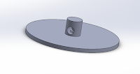 |
| Rotating Plate (Top View) |
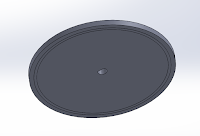 |
| Rotating Plate (Bottom View) |
 |
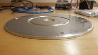
| Base Plate |
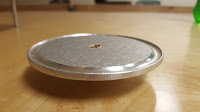
First we designed the pieces of the upper chassis in Solidworks. The main disk was designed first with a diameter of 6 inches, two inches smaller than the disk of the lower chassis. The upper chassis disk was made smaller in order to conserve on weight. However, it still needed to be large enough to keep stability and not interfere with the components housed below. In order to attach this disk to the lower chassis we drilled 8-32 sized holes 120 degrees apart in both chassis' we the used these holes to fasten standoffs securing the two pieces together. In order for the rotating plate to spin stably we designed a channel for bearings to sit in. The channel was cut into the top half of the bottom plate and mirrored on the bottom face of the rotating plate.
 |
| Channel for bearings can be seen at the center |
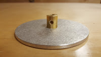 |
| Rotating plate with turned brass centerpiece |
 |
| Channel for bearing on the bottom face |
The stepper motor that drives the head is fastened to the four holes milled into the center of the base plate. The shaft of the motor extends through the center hole and through the center piece on the rotating plate. A set screw fastens the rotating plate to the shaft of the motor holding the assembly together. The rotating plate then rests on the bearings allowing for a smooth turning motion.
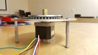 |
The entire assembly
|
A vertical shaft then fits over the turned brass centerpiece. Magnets were placed on the top of this shaft that line up with magnets posted on the bottom of the head chassis. The magnets hold the head on to the shaft while allowing the ball to move.


Comments
Post a Comment